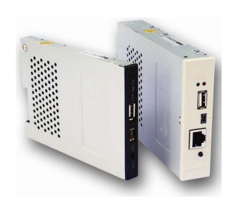
USB Floppy Dipswitch Configuration Chart
This chart describes what each dipswitch does on the usual model of drive. A more complete description is on the technical page, and a list of floppy drives and usual settings for each drive is also available in the links at the bottom.
| Dipswitch | Description |
|---|---|
| DSW 8, DSW7 | These dipswitches together set the maximum size of the emulated floppy disk, usually 720kb or 1.44mb, and the data rate that is seen on the read/write lines. No other dipswitch controls the data rate, so our main concern, after setting this switch, is to properly set the HD OUT line, if it exists (and is required) on your model of machine. It is usually on pin2 or pin4, and may be either high (for 720kb) and low (for 1.44mb), or vice-versa; some disk drives gave the option to invert the signal. It is safest to first try your system at 720kb, since every system should at least support a double density drive, and then to try to match the HD signal with the other dipswitches. Again, many host systems don’t care and can figure out for themselves what kind of data rate is coming in. The FAT12 file system structure will also be different for each setting. The order is: DSW8, DSW7
|
| DSW 6 | This is not used in most USB Floppy units, except for the 2-SY and 1-G series, because of the extended non-dos formats they are capable of. The 1-G is obsolete, use the 1-SY for both dos and non-dos capabilities. Turn it OFF for DOS modes in the SY model. This pin is unused in other models. |
| DSW 5 | This is the DRIVE SELECT configuration switch. It will make the USB Floppy respond to either DRIVE A, or DRIVE B signals (in the IBM unit), or it will respond to the DS0 or DS1 signal (in the 1-SW and all other units.) These two behaviors are slightly cross-compatible; setting the dipswitch to DS1 makes it compatible with the computer PC-style of DRIVE B. Set the dipswitch OFF for DS1/DRIVE B, and set the dipswitch ON for DS0/DRIVEA (again, DS0/DRIVEA are NOT compatible with each other, please be sure your drive is matched to your host system by letting us know what kind of floppy drive you have.). |
| DSW 4 | This signal directly toggles the line on pin 4 of the electrical interface. This is not a popular line, usually mostly for HD if pin2 and pin34 are already in use, otherwise unconnected. It deserves some attention if dipswitches 1-3 do not have enough of an effect. The dipswitch OFF leaves the pin4 line HIGH, and dipswitch ON forces the pin4 line LOW. |
| DSW 3, DSW2, DSW1 | These lines act in conjuction to do the bulk of the optional interface line configuration.
The order is: DSW3, DSW2, DSW1
Many machines will use one of two configurations: 1. DISKCHANGE on pin 34, and HIGH on pin 2. |
Dipswitch Order of Importance
1. Dipswitch 5 (Green light or no green light)
2. Dipswitch 7+8 (Data rate of 720kb or 1.44mb)
3. Dipswitch 1+2+3 (Option configuration)
4. Dipswitch 4 (Rare Option)

